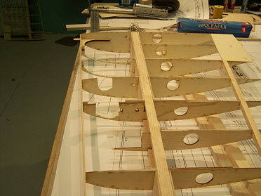
Written update 1/01/08 by: John Monaghan for Meister Scale Models. This is a very simple process to do all the parts that are set to help you achieve a more scale aircraft and have a more reliable landing gear. Utilizing your standard set of plans, all you have to do is swap out the parts. The parts are what make the change of the location of the gear due to the longer length of the struts in the Sierra Retracts as opposed to the original designed retract installation. The process is as follows: You
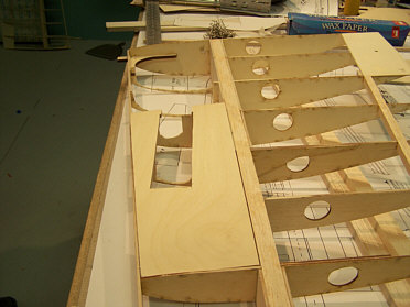
change out ribs W2, W3, W4, W5, W5A, W6, W7A and the gear plate. The
new gear plate is extended from W7A to W4 utilizing a bigger surface
for the larger retract mount frame. In doing this process, you no
longer use the hardwood ½” x ½” rails that
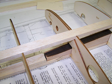
go from leading edge to the main spar. You will use a ¼”
x ½” piece of hardwood for blind nuts on the top side of
the gear plate. You will no longer use the 1/8” balsa sub
leading edge. This will be replaced with 1/8” aircraft ply
recommended from wing rib W1 to W8. You need to use 1/8”
plywood sheer webs on the leading edge side of the main spar from W1
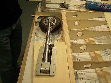
through W7A. The correct gear plate angle is set in the doublers and
the ribs. When installing the retract to the gear plate, you will
need to use button head style machine screws and the best for this is
8/32. You may need to shim the retract on the plate towards the tip
and this will help the retract in the closed position so that the
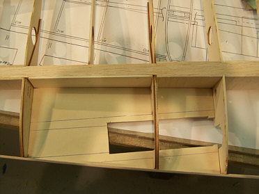
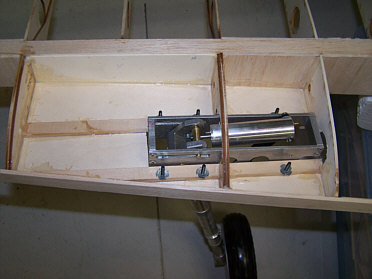
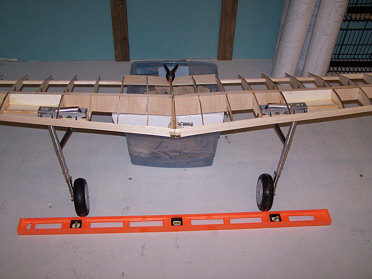
wheel will sit deeper in the wheel well. Don’t worry if the
wheel sits down a little in the closed position. Due to moving the
gear in one rib space, the wheel is now in the belly pan section of
the wing closest to the root rib so you will have plenty of
clearance. As for the forward angle in the gear down position, this
has been set in the parts so the angle should be correct.
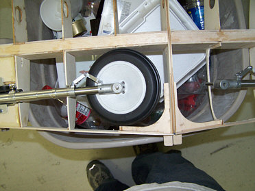
On the
prototype both Sierra’s 6” wheel and the Glennis 5-1/2”
scale wheels were tried. The Glennis 5-1/2” wheel fit the best
out of the two and is more scale, but the choice is yours. After all
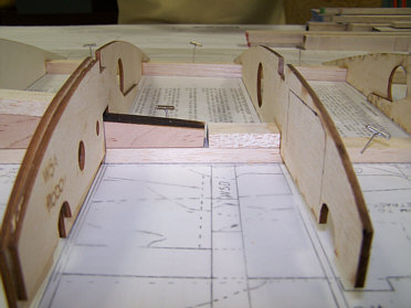
is installed, you will need to use some 1/8” Balsa to fill in
the bottom of the ribs on W5 and W6. In order for the sheeting to be
outlined around the retracts, it might also be helpful to add some
Balsa in between the same ribs. On the prototype wing, the balsa was
notched so that it sat on top of the retract mounting flange, but it
is your choice to do so in case you would ever need to remove the
gear. You will need to lengthen the upper part of the gear door for
the installation of the gear door. This is done by taking the
standard size gear door that may come as a cut part in your kit, and
measure in at the top 11/4” and cut and splice a piece of ply
to lengthen the door to the proper fit.
We hope that this will help you in achieving a simple and less stressful installation.
| |
 |
 |
 |
 |
 |
 |
 |
 |
 |
|